

04Sep
ESP32 with 2 channel relay module
ESP32 with 2 channel relay module tutorial
Hardware Setup:
Gather the necessary components:
- ESP32 development board
- 2-channel relay module
- Jumper wires
- Breadboard (optional)
- Power supply (3.3V or 5V)
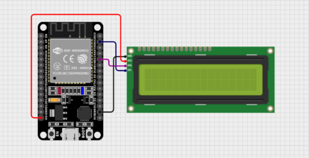
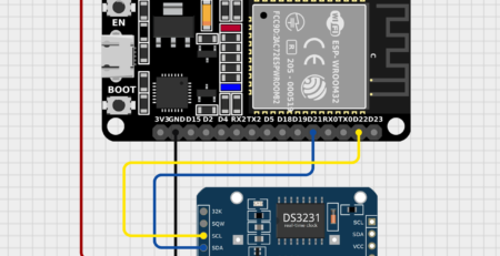
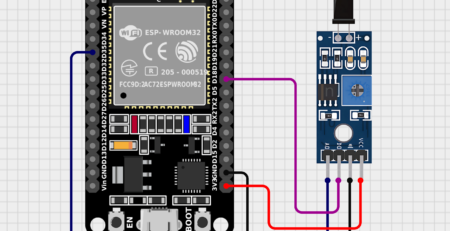
Connect the ESP32 to the relay module:
- Connect the relay module’s input pins to the ESP32’s GPIO pins (e.g., GPIO13 and GPIO14).
- Connect the relay module’s power supply to the ESP32’s 3.3V or 5V output.
- Connect the ground pins of the ESP32 and relay module together.
Software Setup:
- Install the Arduino IDE: Download and install the Arduino IDE from [invalid URL removed].
- Install the ESP32 board support package: Open the Arduino IDE, go to File > Preferences, and add the following URL to the Additional Boards Manager URLs field:
https://dl.espressif.com/package/esp32/index.json. Then, go to Tools > Board > Boards Manager and install the “ESP32” board. - Create a new Arduino sketch: Open the Arduino IDE and create a new sketch.
Code: C++
#include <ESP32.h>

const int relay1Pin = 18;
const int relay2Pin = 19;

void setup(){
  pinMode(relay1Pin, OUTPUT);
  pinMode(relay2Pin, OUTPUT);
}

void loop(){
  // Control relay 1
  digitalWrite(relay1Pin, HIGH); // Turn relay 1 on
  delay(1000); // Wait for 1 second
  digitalWrite(relay1Pin, LOW); // Turn relay 1 off
  delay(1000);

  // Control relay 2
  digitalWrite(relay2Pin, HIGH); // Turn relay 2 on
  delay(1000);
  digitalWrite(relay2Pin, LOW); // Turn relay 2 off
  delay(1000);
}
Explanation:
- The code includes the
ESP32library to provide specific functions for the ESP32. - The
relay1Pinandrelay2Pinvariables define the GPIO pins connected to the relay module’s input pins. - In the
setup()function, the GPIO pins are initialized as outputs. - In the
loop()function, the code repeatedly controls the relays by setting the output pins to HIGH (on) and LOW (off) using thedigitalWrite()function. Thedelay()function is used to introduce a pause between switching the relays.
Uploading the Code:
- Connect the ESP32 to your computer.
- Select the correct board and port in the Arduino IDE.
- Compile and upload the code to the ESP32.
Testing:
- Power on the ESP32 and relay module.
- Observe the connected devices to verify if they are being controlled by the relays as expected.
Additional Notes:
- You can customize the code to control the relays based on different conditions, such as sensor inputs or external commands.
- For more complex applications, consider using libraries like
WiFiManagerfor network configuration orBlynkfor remote control. - Ensure that the relay module’s ratings are suitable for the devices you want to control.
- If you encounter issues, check the wiring, power supply, and code for errors.
By following these steps, you can effectively use an ESP32 to control external devices through a 2-channel relay module.


Leave a Reply
You must be logged in to post a comment.