

16Dec
ESP32 with Dot Matrix Display (MAX7219)
📌 What is the Dot Matrix Display with MAX7219?
A Dot Matrix Display is an arrangement of LEDs in a grid (commonly 8×8) used to display text, symbols, numbers, or animations. When combined with the MAX7219 driver chip, it becomes much easier to control multiple displays using just 3 wires (SPI) from the ESP32.
🧠 Key Features of Dot Matrix with MAX7219
| Feature | Details |
|---|---|
| Display Type | LED Dot Matrix (8×8 per module) |
| Module Driver | MAX7219 |
| Interface | SPI-compatible (DIN, CLK, CS) |
| Voltage | 5V (logic safe for ESP32) |
| Cascadable | Yes (multiple modules side-by-side) |
| Control Library | MD_Parola / MD_MAX72xx |
| Brightness Control | Yes (adjustable via software) |
⚙️ Pinout of MAX7219 Matrix Module
| Pin Name | Description |
|---|---|
| VCC | Power supply (5V) |
| GND | Ground |
| DIN | Data In (to ESP32 MOSI) |
| CS | Chip Select (to GPIO) |
| CLK | Clock (to ESP32 SCK) |
You can daisy-chain multiple displays by connecting
DOUTof one toDINof the next.
📦 How It Works
The MAX7219 is a serial-in, parallel-out LED driver chip. It handles:
- Multiplexing all 64 LEDs (8×8)
- Current control
- Character shifting
- Brightness levels
The ESP32 sends commands/data over SPI to update the matrix content.
🧪 Applications of Dot Matrix Display
- Digital clocks and counters
- Scrolling message displays (like LED banners)
- IoT status dashboards
- Sensor value display
- Simple games (like snake, pong)
- Notification boards
- Temperature/humidity/weather display
🔗 Basic Example with ESP32
✅ Components Needed
- ESP32 board
- MAX7219 8×8 LED Matrix module
- Jumper wires
- Breadboard (optional)
- Power source (5V via USB or external)
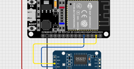
🔌 Wiring MAX7219 Matrix with ESP32 (SPI)
| MAX7219 Pin | ESP32 Pin |
|---|---|
| VCC | 5V |
| GND | GND |
| DIN | GPIO23 (MOSI) |
| CS | GPIO5 |
| CLK | GPIO18 (SCK) |
🧾 ESP32 Code with MAX7219 Matrix (Scrolling Text)
HOW TO OPERATE

// ESP32  MAX7219 Module
// 5V VCC
// GND  GND
// GPIO18 CLK
// GPIO5  CS
// GPIO23 DIN


#include "MD_Parola.h"
#include "MD_MAX72xx.h"
#include "SPI.h"

// Uncomment according to your hardware type
#define HARDWARE_TYPE MD_MAX72XX::FC16_HW
//#define HARDWARE_TYPE MD_MAX72XX::GENERIC_HW

// Defining size, and output pins
#define MAX_DEVICES 4
#define CS_PIN 5

MD_Parola disp = MD_Parola(HARDWARE_TYPE, CS_PIN, MAX_DEVICES);

void setup() {
  disp.begin();
  disp.setIntensity(0);
  disp.displayClear();
}

void loop() {
  disp.setTextAlignment(PA_LEFT);
  disp.print("ESP32");
  delay(2000);

  disp.setTextAlignment(PA_CENTER);
  disp.print("ESP32");
  delay(2000);

  disp.setTextAlignment(PA_RIGHT);
  disp.print("ESP32");
  delay(2000);

  disp.setTextAlignment(PA_CENTER);
  disp.setInvert(true);
  disp.print("ESP32");
  delay(2000);

  disp.setInvert(false);
  delay(2000);
}❗ Important Notes
- You must use level shifters or be cautious with logic levels. MAX7219 is tolerant to ESP32’s 3.3V.
- Connect modules in correct direction (check DIN/DOUT labeling).
- Use external 5V power for more than 4 modules.
- MAX_DEVICES must match the number of chained matrices.

Leave a Reply
You must be logged in to post a comment.