

12Dec
ESP32 with L298N DC Motor Driver
- 08-06-2025
🔧 Basic Introduction
- L298N is a dual H-Bridge motor driver IC that allows controlling the direction and speed of two DC motors or one stepper motor.
- It operates on high voltage and high current, making it suitable for robotics and mechatronics applications.
⚙️ Technical Specifications
- Operating Voltage: 5V to 35V (Motor supply); 5V logic supply.
- Current Handling: Up to 2A per channel continuously.
- Logic Level Inputs: Compatible with 5V logic (Arduino, ESP32, etc.).
- Heat Sink: Comes with a built-in heat sink to dissipate heat during high load.
- Control Pins: IN1, IN2, IN3, IN4 to control motor direction.
- Enable Pins (EN): ENA and ENB to control speed using PWM (Enable A for Motor A; Enable B for Motor B).
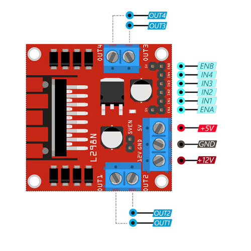
🔌 Pin Description
- IN1 & IN2: Control Motor A direction.
- IN3 & IN4: Control Motor B direction.
- ENA (Enable A): Controls speed of Motor A using PWM.
- ENB (Enable B): Controls speed of Motor B using PWM.
- VCC: Power for motors (up to 35V).
- 5V: Logic voltage supply (can be from onboard 5V regulator or external).
- GND: Ground connection.
- OUT1 & OUT2: Outputs for Motor A.
- OUT3 & OUT4: Outputs for Motor B.
⚡ Working Principle
- Uses H-Bridge configuration to allow voltage to flow in either direction, enabling forward and reverse motor motion.
- Direction is controlled by logic levels on INx pins.
- Speed is controlled via PWM (Pulse Width Modulation) on the ENA and ENB pins.
🔄 Direction Logic Table
| IN1 | IN2 | Motor A Direction |
|---|---|---|
| HIGH | LOW | Forward |
| LOW | HIGH | Reverse |
| LOW | LOW | Stop |
| HIGH | HIGH | Stop/Brake |
(Similar logic applies to IN3 and IN4 for Motor B)
✅ Advantages
- Can control two motors independently.
- Built-in protection diodes to handle back EMF from motors.
- Low cost and easily available.
- Compatible with Arduino, ESP32, Raspberry Pi, etc.
HOW TO OPERATE L298N DC MOTOR
#define IN1 18
#define IN2 19
#define IN3 13
#define IN4 12


void setup() {
  pinMode(IN1,OUTPUT);
  pinMode(IN2,OUTPUT);
  pinMode(IN3,OUTPUT);
  pinMode(IN4,OUTPUT);


}


void loop() {


  // Forward Wise
   digitalWrite(IN1,HIGH);
   digitalWrite(IN2,LOW);


  //  Backward Wise
   digitalWrite(IN3,LOW);
   digitalWrite(IN4,HIGH);


  //  HIGH HIGH , LOW LOW  (BREAK)
   digitalWrite(IN3,LOW);
   digitalWrite(IN4,LOW);


}


Leave a Reply
You must be logged in to post a comment.