

MAX7219 7-Segment Display with ESP32
Introduction
In this tutorial, we will learn how to interface a MAX7219 8-Digit 7-Segment Display with an ESP32 using the LedController Library. This project displays numbers from 0 to 7 on the 7-segment display sequentially. We will also explore the capabilities of the MAX7219 ESP32 integration and its applications.
The MAX7219 is a popular display driver IC that simplifies controlling multiple 7-segment displays using only three communication pins. It is widely used in digital clocks, counters, scoreboards, IoT dashboards, and industrial monitoring systems.
The MAX7219 ESP32 is becoming increasingly popular among developers for its ease of use, versatility, and its ability to interface with various components in IoT projects.
The MAX7219 ESP32 combination is ideal for various applications, allowing for efficient display management and control while making it suitable for beginners and advanced users alike.
This combination of MAX7219 ESP32 allows for efficient display management and control across multiple platforms.
Components Required
- ESP32 Development Board
- MAX7219 8-Digit 7-Segment Display Module
- Jumper Wires
- USB Cable
- Arduino IDE
Understanding MAX7219
The MAX7219 is a serial input/output common-cathode display driver that can control:
- 8-digit 7-segment displays
- LED matrices
- Numeric displays
Features
- Uses only 3 communication pins
- Adjustable brightness
- Supports cascading multiple modules
- Low wiring complexity
- Fast data transmission
Circuit Diagram
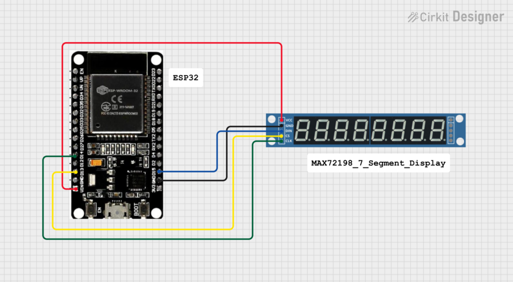
| MAX7219 Pin | ESP32 Pin |
|---|---|
| VCC | 5V |
| GND | GND |
| DIN | GPIO 15 |
| CLK | GPIO 14 |
| CS/LOAD | GPIO 13 |
Wiring Overview
ESP32                MAX7219
-----------------------------
5V      -----------> VCC
GND     -----------> GND
GPIO15  -----------> DIN
GPIO14  -----------> CLK
GPIO13  -----------> CS
Understanding the Define Statements
#define DIN 15
#define CS 13
#define CLK 14
What is DIN?
#define DIN 15
DIN stands for Data Input.
The ESP32 sends display data through GPIO 15 to the MAX7219.
What is CLK?
#define CLK 14
CLK stands for Clock Pin.
This pin synchronizes data transmission between ESP32 and MAX7219.
What is CS?
#define CS 13
CS stands for Chip Select or LOAD.
It tells the MAX7219 when to accept incoming data.
Installing the LedController Library
Step 1: Open Arduino IDE
Launch Arduino IDE.
Step 2: Open Library Manager
Navigate to:
Sketch → Include Library → Manage Libraries
Step 3: Search Library
Search for:
LedControllerStep 4: Install
Install the LedController Library by Noa Sakurajin.
Complete Code
/**
* @file LCDemo7Segment.ino
* @author Noa Sakurajin
* @brief Using MAX7219 with 7-Segment Display
*/
#include "LedController.hpp"
#define DIN 15
#define CS 13
#define CLK 14
LedController<1,1> lc;
unsigned long delaytime = 1000;
void setup() {
lc = LedController<1,1>(DIN, CLK, CS);
lc.setIntensity(8);
lc.clearMatrix();
}
void loop() {
for(int i = 0; i < 8; i++) {
lc.setDigit(0, i, i, false);
delay(delaytime);
}
lc.clearMatrix();
delay(delaytime);
}
Code Explanation
Include Library
#include "LedController.hpp"
Loads the LedController library required for communication with MAX7219.
Create Display Object
LedController<1,1> lc;
Parameters:
<1,1>
Mean:
- 1 Row
- 1 Display Module
If multiple MAX7219 modules are cascaded, these values can be increased.
Initialize Display
lc = LedController<1,1>(DIN, CLK, CS);
Creates a controller object using software SPI communication.
Set Brightness
lc.setIntensity(8);
Brightness range:
0 = Minimum
15 = Maximum
Value 8 provides medium brightness.
Clear Display
lc.clearMatrix();
Turns off all segments.
Display Digits
lc.setDigit(0,i,i,false);
Parameters:
setDigit(address, position, digit, decimalPoint)
| Parameter | Description |
|---|---|
| address | Display address |
| position | Digit position |
| digit | Number to display |
| decimalPoint | true/false |
Example:
lc.setDigit(0,3,5,false);
Displays digit 5 at position 3.
Program Output
The display will show:
0
1
2
3
4
5
6
7
One digit appears every second.
After displaying all digits:
Display Clears
The cycle repeats continuously.
Applications
- Digital Clock-Display hours, minutes, and seconds.
- Visitor Counter-Count entries in offices, malls, and events.
- Industrial Monitoring-Display sensor readings and machine parameters.
- IoT Dashboards-Show live sensor data from cloud-connected devices.
- Scoreboard Systems-Display scores in sports and gaming projects
.
Troubleshooting
Display Not Working
Check:
- VCC connection
- GND connection
- DIN wiring
- CLK wiring
- CS wiring
Random Digits Appearing
Verify:
#define DIN 15
#define CLK 14
#define CS 13
match your actual wiring.
Display Too Dim
Increase brightness:
lc.setIntensity(15);
Advantages of MAX7219
- Requires only 3 GPIO pins
- Supports multiple displays
- Adjustable brightness
- Low CPU usage
- Easy integration with ESP32 and Arduino
Conclusion
Using the MAX7219 with ESP32 is one of the easiest ways to control 7-segment displays. With the LedController library, developers can quickly create counters, clocks, monitoring systems, and IoT dashboards while using minimal GPIO pins. This project demonstrates basic digit display functionality and serves as a foundation for more advanced applications.


Leave a Reply
You must be logged in to post a comment.