

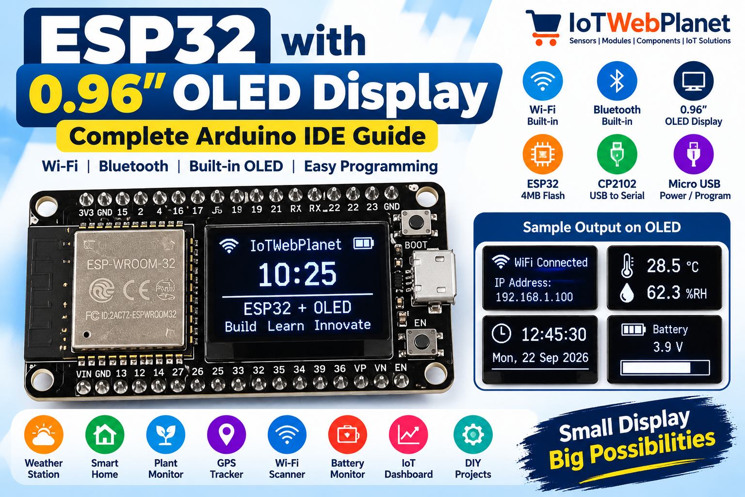
ESP32 with 0.96 Inch OLED Display – Arduino IDE Programming Guide
The ESP32 with 0.96-inch OLED display combines an ESP32 Wi-Fi/Bluetooth controller, an integrated white OLED screen and CP2102 USB-to-serial interface on one compact development board. It is ideal for portable IoT devices that need both wireless connectivity and a local display.
Components Required
- ESP32 with 0.96-inch OLED – Buy from IoTWebPlanet
- Micro-USB data cable
- Computer with Arduino IDE
- Optional sensors/modules for your project
Key Features and Specifications
| Controller | ESP32 |
| Display | Integrated 0.96-inch white OLED |
| Flash | 4 MB |
| Wireless | Wi-Fi + Bluetooth |
| USB interface | CP2102 |
| Programming/Power | Micro-USB |
| Digital pins | Up to 19 |
| Analog pins | Up to 11 |
| Wi-Fi modes | AP, STA, AP+STA |
Why Use ESP32 with Built-in OLED?
The integrated display is useful when an IoT project needs immediate local feedback without wiring a separate screen. You can show sensor readings, Wi-Fi status, IP address, battery condition, alerts, menus and compact dashboards directly on the device.
OLED Connection
The OLED is already integrated on the PCB, so no external VCC/GND/SDA/SCL jumper wiring is required. Integrated ESP32/OLED boards can use board-specific internal I2C pins, so confirm the board pinout or scan the I2C bus before assuming generic GPIO21/GPIO22 wiring.
Conceptual Wiring Diagram
       ESP32 + 0.96" OLED BOARD
┌────────────────────────────────┐
│ Micro USB → CP2102 → ESP32     │
│                       │        │
│                       │ I2C    │
│                       ▼        │
│                ┌───────────┐   │
│                │0.96" OLED│   │
│                └───────────┘   │
└────────────────────────────────┘
Required Arduino Libraries
- Adafruit GFX Library
- Adafruit SSD1306
- Wire (included with ESP32 Arduino core)
Step 1: Find the OLED I2C Address
#include <Wire.h>

void setup() {
  Serial.begin(115200);
  Wire.begin();
  Serial.println("Scanning I2C bus...");

  for (byte address = 1; address < 127; address++) {
    Wire.beginTransmission(address);
    if (Wire.endTransmission() == 0) {
      Serial.print("I2C device found at 0x");
      if (address < 16) Serial.print("0");
      Serial.println(address, HEX);
    }
  }
}

void loop() {}
Complete ESP32 OLED Example Code
#include <Wire.h>
#include <Adafruit_GFX.h>
#include <Adafruit_SSD1306.h>

#define SCREEN_WIDTH 128
#define SCREEN_HEIGHT 64
#define OLED_SDA 21
#define OLED_SCL 22
#define OLED_ADDR 0x3C

Adafruit_SSD1306 display(SCREEN_WIDTH, SCREEN_HEIGHT, &Wire, -1);

void setup() {
  Serial.begin(115200);
  Wire.begin(OLED_SDA, OLED_SCL);

  if (!display.begin(SSD1306_SWITCHCAPVCC, OLED_ADDR)) {
    Serial.println("OLED initialization failed.");
    while (true) delay(100);
  }

  display.clearDisplay();
  display.setTextColor(SSD1306_WHITE);
  display.setTextSize(1);
  display.setCursor(0, 0);
  display.println("IoTWebPlanet");
  display.println("ESP32 + OLED");
  display.display();

  Serial.println("OLED initialized successfully.");
}

void loop() {
  static unsigned long counter = 0;
  display.clearDisplay();
  display.setTextSize(1);
  display.setCursor(0, 0);
  display.println("IoTWebPlanet");
  display.println("----------------");
  display.println("ESP32 + OLED");
  display.println();
  display.print("Uptime: ");
  display.print(counter);
  display.println(" sec");
  display.display();
  counter++;
  delay(1000);
}
Important: GPIO21/GPIO22 and address 0x3C above are common ESP32/OLED defaults, not a guarantee of the internal routing of SKU IWP-01509. Confirm the actual board pinout/address and change the definitions if required.
How the Code Works
Wire initializes I2C communication. The SSD1306 library creates a framebuffer for the display. Text is prepared with setCursor(), setTextSize() and print/println(), while display.display() transfers the framebuffer to the OLED. The loop updates an uptime counter once per second.
Expected Output
IoTWebPlanet
----------------
ESP32 + OLED

Uptime: 25 sec
Troubleshooting
- OLED blank: Confirm board-specific SDA/SCL pins and I2C address.
- OLED detected but no text: Verify the display controller/library; visually similar modules may use different controllers.
- Adafruit_SSD1306.h missing: Install Adafruit SSD1306 and Adafruit GFX Library.
- No serial port: Check the USB data cable and CP210x driver.
- Upload fails: Verify the selected ESP32 board and serial port, and use BOOT if required.
15 Practical Project Ideas
- Wi-Fi signal strength meter
- Portable IoT weather station
- ESP32 internet clock
- Temperature and humidity monitor
- Air-quality monitor
- Battery monitoring display
- Smart plant monitor
- Wi-Fi network scanner
- MQTT status display
- Stock or cryptocurrency display
- Water-tank level monitor
- GPS speedometer
- Bluetooth device scanner
- Smart classroom environment monitor
- Portable sensor diagnostic tool
Frequently Asked Questions
Does this ESP32 board already contain an OLED?
Yes. IoTWebPlanet SKU IWP-01509 includes an integrated white 0.96-inch OLED display.
Does it support Wi-Fi and Bluetooth?
Yes. Both Wi-Fi and Bluetooth are features of the ESP32 board.
How much flash memory does it have?
The product listing specifies 4 MB flash memory.
Can it be programmed with Arduino IDE?
Yes. Its CP2102 USB-to-serial interface supports straightforward programming from Arduino IDE.
Do I need a separate OLED module?
No. The 0.96-inch OLED is integrated into the board.
Conclusion
The ESP32 with integrated 0.96-inch OLED is a convenient platform for compact connected projects. It combines wireless connectivity, processing and a local user interface on a single board, making it suitable for portable sensor nodes, monitors, diagnostic tools and IoT dashboards.





Leave a Reply
You must be logged in to post a comment.