

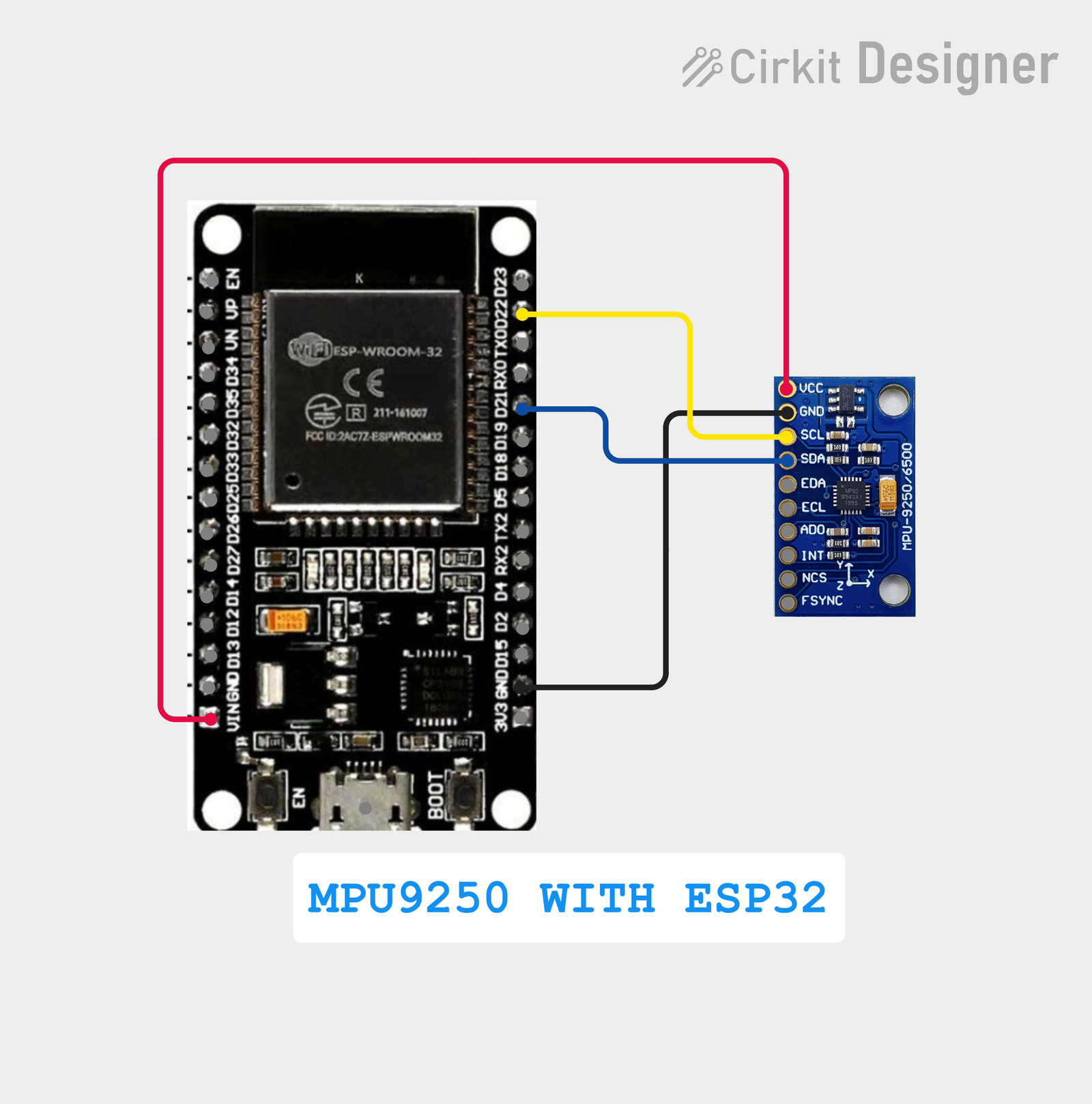
MPU9250 with ESP32: Complete Guide to Accelerometer, Gyroscope and Magnetometer
The MPU9250 is a powerful 9-axis motion sensor that combines a 3-axis accelerometer, 3-axis gyroscope, and 3-axis magnetometer in a single compact module. It is widely used in robotics, drones, IoT devices, navigation systems, motion tracking, balancing robots, wearable electronics, and embedded systems.
In this tutorial, we will learn how to interface MPU9250 with ESP32 using I2C, read accelerometer, gyroscope, and magnetometer data, understand the MPU9250 registers, and write a complete Arduino IDE program.
This guide is suitable for beginners as well as students and developers working on ESP32 IoT and robotics projects.
Table of Contents
- What is MPU9250?
- MPU9250 Features
- MPU9250 Sensor Specifications
- How MPU9250 Works
- MPU9250 Pinout
- MPU9250 and ESP32 I2C Communication
- MPU9250 I2C Address
- MPU9250 Circuit Diagram
- Components Required
- Wiring MPU9250 with ESP32
- Installing Arduino IDE
- Complete MPU9250 ESP32 Code
- Code Explanation
- Reading Accelerometer Data
- Reading Gyroscope Data
- Reading Magnetometer Data
- Understanding WHO_AM_I
- Understanding MPU9250 Registers
- Understanding Acceleration in g
- Understanding Gyroscope Data in °/s
- Magnetometer Data and Heading
- How to Calculate Orientation
- MPU9250 Applications
- Common Problems and Troubleshooting
- Conclusion
What is MPU9250?
The MPU9250 is a 9-axis MEMS motion tracking sensor manufactured by InvenSense. It integrates three different sensing systems:
- 3-axis accelerometer
- 3-axis gyroscope
- 3-axis magnetometer
Because it provides nine degrees of freedom, the MPU9250 is commonly called a 9-axis IMU (Inertial Measurement Unit).
The accelerometer measures linear acceleration, the gyroscope measures angular velocity, and the magnetometer measures the surrounding magnetic field.
When these three sensors are combined with appropriate sensor fusion algorithms, the MPU9250 can be used to estimate the orientation and movement of a device.
MPU9250 Features
Some important features of the MPU9250 include:
- 9-axis motion sensing
- 3-axis accelerometer
- 3-axis gyroscope
- 3-axis magnetometer
- I2C and SPI communication
- Low power consumption
- Compact size
- Digital sensor interface
- Programmable accelerometer ranges
- Programmable gyroscope ranges
- Temperature sensor
- Motion detection capabilities
- Suitable for embedded systems
- Compatible with ESP32
- Compatible with Arduino
- Useful for robotics and drones
The combination of an accelerometer, gyroscope, and magnetometer makes the MPU9250 particularly useful for applications where orientation and motion need to be measured.
MPU9250 Sensor Specifications
| Sensor | Measurement |
|---|---|
| Accelerometer | 3-axis |
| Gyroscope | 3-axis |
| Magnetometer | 3-axis |
| Total axes | 9-axis |
| Communication | I2C / SPI |
| Accelerometer default range | ±2g |
| Gyroscope default range | ±250 °/s |
| I2C MPU address | 0x68 / 0x69 |
| Magnetometer address | 0x0C |
| Logic level | Depends on module |
| Interface | Digital |
The exact electrical specifications can vary depending on the MPU9250 breakout board being used.
How Does MPU9250 Work?
The MPU9250 contains multiple MEMS sensors inside one IC.
1. Accelerometer
The accelerometer measures acceleration along:
- X-axis
- Y-axis
- Z-axis
When the sensor is stationary, gravity is detected by the accelerometer. Therefore, the accelerometer can be used to estimate the tilt of the sensor.
For example:
Flat sensor:

X → 0 g
Y → 0 g
Z → approximately 1 g
The exact values can vary because of sensor orientation, calibration, and noise.
2. Gyroscope
The gyroscope measures angular velocity around the three axes:
X → Roll
Y → Pitch
Z → Yaw
Its output is normally represented in:
degrees per second (°/s)
A gyroscope is useful for detecting how quickly the sensor is rotating.
3. Magnetometer
The magnetometer measures the Earth’s magnetic field along three axes.
It can be used as a digital compass to determine magnetic heading.
The MPU9250 commonly uses the AK8963 magnetometer internally.
MPU9250 Pinout
A typical MPU9250 breakout board may contain the following pins:
| MPU9250 Pin | Function |
|---|---|
| VCC | Power |
| GND | Ground |
| SCL | I2C Clock |
| SDA | I2C Data |
| AD0 | I2C Address Selection |
| INT | Interrupt |
Some breakout boards have additional pins such as FSYNC or ECL.
Always check the pin labels on your specific module before connecting it.
MPU9250 with ESP32 Using I2C
The ESP32 supports I2C communication and allows the SDA and SCL pins to be selected in software.
In this project, we use:
#define SDA_PIN 21
#define SCL_PIN 22
Therefore:
ESP32 GPIO 21 → MPU9250 SDA
ESP32 GPIO 22 → MPU9250 SCL
ESP32 GND → MPU9250 GND
ESP32 VCC → MPU9250 VCC
The ESP32 communicates with the MPU9250 using the I2C protocol.
MPU9250 I2C Address
The MPU9250 normally uses:
0x68
when the AD0 pin is LOW.
It can also use:
0x69
when AD0 is HIGH.
The AK8963 magnetometer normally uses:
0x0C
In this project, the addresses are defined as:
#define MPU9250_ADDR 0x68
#define AK8963_ADDR 0x0C
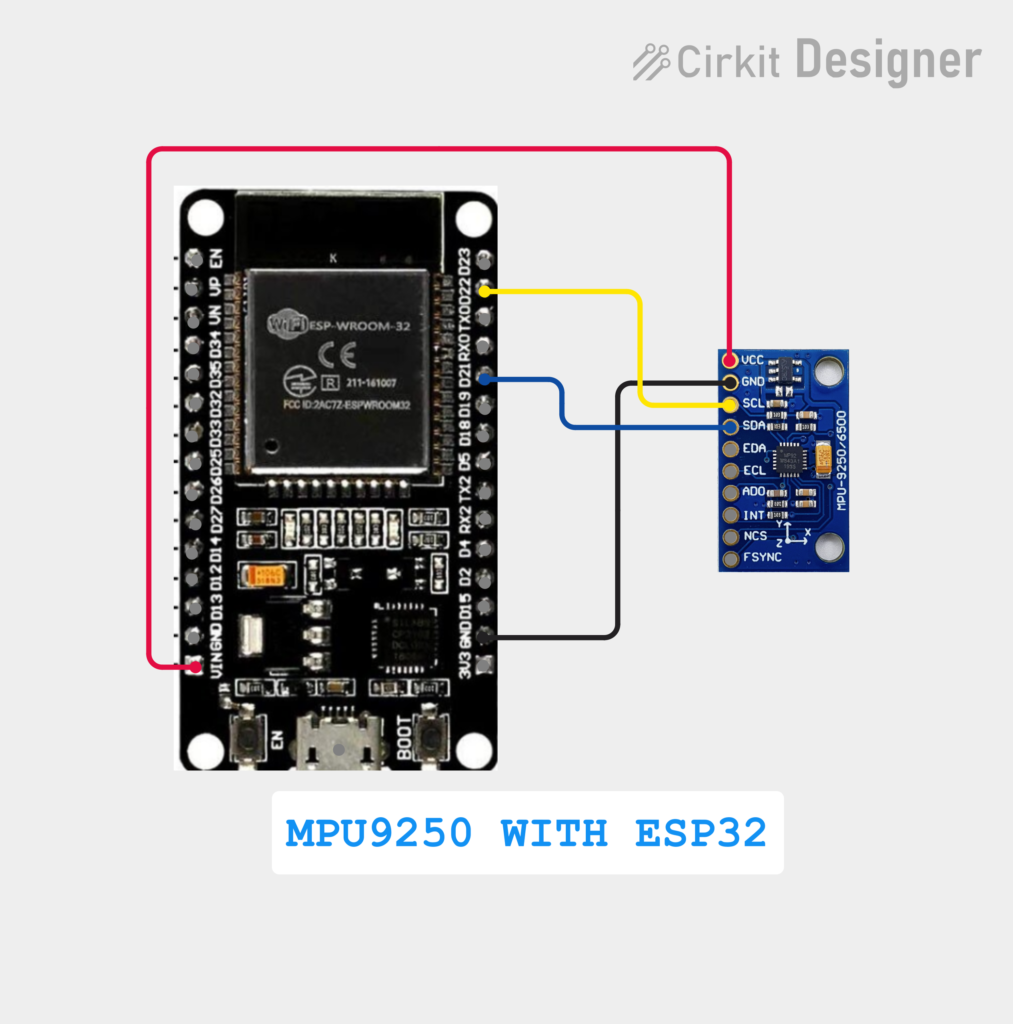
MPU9250 Circuit Diagram
ESP32 to MPU9250 Wiring
[INSERT MPU9250 + ESP32 CIRCUIT DIAGRAM HERE]
Suggested diagram:
ESP32
┌──────────────┐
│ │
│ GPIO 21 SDA ───────── SDA
│ GPIO 22 SCL ───────── SCL
│ │
│ GND ──────────────── GND
│ │
│ 3.3V ─────────────── VCC
│ │
└──────────────┘
MPU9250
Circuit Diagram Space: Add a clear labeled image showing ESP32 GPIO 21, GPIO 22, 3.3V, GND, SDA, and SCL connections to the MPU9250.
Components Required
To build this project, you need:
- ESP32 development board
- MPU9250 sensor module
- Jumper wires
- Breadboard
- USB cable
- Computer
- Arduino IDE
Optional:
- External power supply
- Enclosure
- Robot or drone platform for practical testing
MPU9250 ESP32 Wiring Table
| ESP32 | MPU9250 |
|---|---|
| GPIO 21 | SDA |
| GPIO 22 | SCL |
| GND | GND |
| 3.3V | VCC |
Important
Before powering the sensor, verify the voltage requirements of your particular MPU9250 breakout board.
Complete MPU9250 ESP32 Code
The following program initializes the MPU9250, reads accelerometer and gyroscope values, and attempts to read the AK8963 magnetometer.
#include <Wire.h>
#define SDA_PIN 21
#define SCL_PIN 22
#define MPU9250_ADDR 0x68
#define AK8963_ADDR  0x0C
// MPU9250 registers
#define WHO_AM_I 0x75
#define PWR_MGMT_1 0x6B
#define ACCEL_XOUT_H 0x3B
#define GYRO_XOUT_H 0x43
// AK8963 magnetometer registers
#define AK8963_WHO_AM_I 0x00
#define AK8963_ST1 0x02
#define AK8963_XOUT_L 0x03
#define AK8963_CNTL1 0x0A
// ---------------- I2C FUNCTIONS ----------------
void writeByte(uint8_t address, uint8_t reg, uint8_t data) {
Wire.beginTransmission(address);
Wire.write(reg);
Wire.write(data);
Wire.endTransmission();
}
uint8_t readByte(uint8_t address, uint8_t reg) {
Wire.beginTransmission(address);
Wire.write(reg);
Wire.endTransmission(false);
Wire.requestFrom(address, (uint8_t)1);
if (Wire.available())
return Wire.read();
return 0;
}
void readBytes(uint8_t address, uint8_t reg,
uint8_t count, uint8_t *data) {
Wire.beginTransmission(address);
Wire.write(reg);
Wire.endTransmission(false);
Wire.requestFrom(address, count);
for (uint8_t i = 0; i < count && Wire.available(); i++) {
data[i] = Wire.read();
}
}
// ---------------- SETUP ----------------
void setup() {
Serial.begin(115200);
Wire.begin(SDA_PIN, SCL_PIN);
delay(1000);
Serial.println("MPU9250 + ESP32");
Serial.println("----------------");
// Wake MPU9250
writeByte(MPU9250_ADDR, PWR_MGMT_1, 0x00);
delay(100);
// Check MPU9250
uint8_t whoami = readByte(MPU9250_ADDR, WHO_AM_I);
Serial.print("MPU9250 WHO_AM_I: 0x");
Serial.println(whoami, HEX);
// Initialize magnetometer
writeByte(AK8963_ADDR, AK8963_CNTL1, 0x00);
delay(10);
// Continuous measurement mode 2
// 100 Hz, 16-bit
writeByte(AK8963_ADDR, AK8963_CNTL1, 0x16);
delay(100);
Serial.println("MPU9250 initialized!");
Serial.println();
}
// ---------------- LOOP ----------------
void loop() {
uint8_t data[14];
// Read accelerometer + temperature + gyroscope
readBytes(MPU9250_ADDR, ACCEL_XOUT_H, 14, data);
int16_t ax = (data[0] << 8) | data[1];
int16_t ay = (data[2] << 8) | data[3];
int16_t az = (data[4] << 8) | data[5];
int16_t gx = (data[8] << 8) | data[9];
int16_t gy = (data[10] << 8) | data[11];
int16_t gz = (data[12] << 8) | data[13];
// Convert to physical values
float accelX = ax / 16384.0;
float accelY = ay / 16384.0;
float accelZ = az / 16384.0;
float gyroX = gx / 131.0;
float gyroY = gy / 131.0;
float gyroZ = gz / 131.0;
// ---------------- MAGNETOMETER ----------------
uint8_t magData[7];
uint8_t magStatus =
readByte(AK8963_ADDR, AK8963_ST1);
int16_t mx = 0;
int16_t my = 0;
int16_t mz = 0;
if (magStatus & 0x01) {
readBytes(AK8963_ADDR,
AK8963_XOUT_L,
7,
magData);
mx = (int16_t)((magData[1] << 8) |
magData[0]);
my = (int16_t)((magData[3] << 8) |
magData[2]);
mz = (int16_t)((magData[5] << 8) |
magData[4]);
}
// ---------------- SERIAL OUTPUT ----------------
Serial.println("========== MPU9250 ==========");
Serial.print("Accelerometer X: ");
Serial.print(accelX, 2);
Serial.print(" g Y: ");
Serial.print(accelY, 2);
Serial.print(" g Z: ");
Serial.print(accelZ, 2);
Serial.println(" g");
Serial.print("Gyroscope X: ");
Serial.print(gyroX, 2);
Serial.print(" °/s Y: ");
Serial.print(gyroY, 2);
Serial.print(" °/s Z: ");
Serial.print(gyroZ, 2);
Serial.println(" °/s");
Serial.print("Magnetometer X: ");
Serial.print(mx);
Serial.print(" Y: ");
Serial.print(my);
Serial.print(" Z: ");
Serial.println(mz);
Serial.println();
delay(500);
}
Understanding the MPU9250 Code
Let’s understand the program section by section.
1. Including the Wire Library
#include <Wire.h>
The Wire library provides I2C communication functionality for the ESP32.
It allows the ESP32 to communicate with sensors such as the MPU9250.
2. Defining I2C Pins
#define SDA_PIN 21
#define SCL_PIN 22
Here:
- GPIO 21 = SDA
- GPIO 22 = SCL
The I2C bus uses two communication lines.
SDA
SDA means:
Serial Data
It carries data between the ESP32 and sensor.
SCL
SCL means:
Serial Clock
It provides the clock signal used for synchronization.
3. Defining Sensor Addresses
#define MPU9250_ADDR 0x68
#define AK8963_ADDR  0x0C
The MPU9250 and AK8963 use different I2C addresses.
MPU9250 → 0x68
AK8963  → 0x0C
This allows the controller to identify which device it wants to communicate with.
4. Waking Up the MPU9250
The MPU9250 can initially start in sleep mode.
The code uses:
writeByte(MPU9250_ADDR, PWR_MGMT_1, 0x00);
The register:
0x6B
is the power management register.
Writing 0x00 clears the sleep bit and wakes the sensor.
5. Checking WHO_AM_I
The code reads:
uint8_t whoami =
    readByte(MPU9250_ADDR, WHO_AM_I);
The WHO_AM_I register is:
0x75
It is useful for verifying communication with the sensor.
The result is printed using:
Serial.print("MPU9250 WHO_AM_I: 0x");
Serial.println(whoami, HEX);
If communication is working, you should receive a valid device identification value.
6. Reading Accelerometer Data
The accelerometer registers begin at:
#define ACCEL_XOUT_H 0x3B
The program reads 14 bytes:
readBytes(MPU9250_ADDR,
          ACCEL_XOUT_H,
          14,
          data);
These bytes contain:
Accelerometer X
Accelerometer Y
Accelerometer Z
Temperature
Gyroscope X
Gyroscope Y
Gyroscope Z
Each sensor axis uses two bytes.
7. Combining High and Low Bytes
The sensor sends each 16-bit value as two bytes.
For example:
int16_t ax =
    (data[0] << 8) | data[1];
Here:
data[0]= high bytedata[1]= low byte
The two bytes are combined into one signed 16-bit integer.
The same technique is used for all axes.
8. Converting Accelerometer Values
The default accelerometer range is typically ±2g.
The sensitivity at ±2g is:
16384 LSB/g
Therefore:
float accelX = ax / 16384.0;
The result is represented in:
g
For example:
X = 0.02 g
Y = -0.01 g
Z = 0.99 g
would indicate that the sensor is approximately stationary with its Z-axis aligned with gravity.
9. Reading Gyroscope Data
The gyroscope starts at:
#define GYRO_XOUT_H 0x43
The 14-byte read already contains the gyroscope values.
The code extracts:
int16_t gx = (data[8] << 8) | data[9];
int16_t gy = (data[10] << 8) | data[11];
int16_t gz = (data[12] << 8) | data[13];
10. Converting Gyroscope Data
At the default ±250 °/s range, the sensitivity is:
131 LSB/(°/s)
Therefore:
float gyroX = gx / 131.0;
float gyroY = gy / 131.0;
float gyroZ = gz / 131.0;
The final output is:
degrees per second
or:
°/s
11. Reading the Magnetometer
The MPU9250 contains an AK8963 magnetometer.
The code defines:
#define AK8963_ST1  0x02
#define AK8963_XOUT_L 0x03
First, the program checks whether new magnetometer data is available:
uint8_t magStatus =
    readByte(AK8963_ADDR, AK8963_ST1);
Then:
if (magStatus & 0x01)
checks the data-ready bit.
If new data is available, the sensor values are read.
12. Magnetometer X, Y and Z
The magnetometer provides three axes:
MX
MY
MZ
The code combines the low and high bytes:
mx = (int16_t)((magData[1] << 8) |
               magData[0]);

my = (int16_t)((magData[3] << 8) |
               magData[2]);

mz = (int16_t)((magData[5] << 8) |
               magData[4]);
These values represent the magnetic field measured by the magnetometer.
Important Note About the Magnetometer
On many MPU9250 breakout boards, the AK8963 magnetometer is internally connected to the MPU9250.
Direct ESP32 access to the AK8963 at address 0x0C may therefore require enabling the MPU9250’s I2C bypass mode.
If the accelerometer and gyroscope work but the magnetometer always returns zero or does not respond, check the MPU9250’s INT_PIN_CFG register and enable I2C bypass mode before accessing the AK8963 directly.
This is an important troubleshooting point when working with MPU9250 + ESP32 magnetometer code.
Understanding MPU9250 Output
A typical Serial Monitor output may look like:
========== MPU9250 ==========

Accelerometer X: 0.02 g
Y: -0.01 g
Z: 0.99 g

Gyroscope X: 0.15 °/s
Y: -0.10 °/s
Z: 0.20 °/s

Magnetometer X: 120
Y: -45
Z: 280
The actual values depend on:
- Sensor orientation
- Calibration
- Noise
- Magnetic interference
- Temperature
- Sensor range
- Environmental conditions
Accelerometer vs Gyroscope vs Magnetometer
| Sensor | Measures | Typical Use |
|---|---|---|
| Accelerometer | Linear acceleration | Tilt, movement, vibration |
| Gyroscope | Angular velocity | Rotation |
| Magnetometer | Magnetic field | Compass/heading |
Using all three sensors together allows more advanced motion tracking.
What Can You Do With MPU9250?
The MPU9250 can be used for many projects.
Robotics
MPU9250 is useful for:
- Self-balancing robots
- Robot orientation
- Motion detection
- Robot navigation
- Vibration monitoring
- Autonomous robots
Drone Projects
It can be used for:
- Drone attitude sensing
- Roll measurement
- Pitch measurement
- Yaw estimation
- Flight controller experiments
- Motion stabilization
IoT Projects
The MPU9250 can be integrated into IoT systems for:
- Remote motion monitoring
- Equipment monitoring
- Smart devices
- Motion-triggered systems
- Industrial monitoring
Wearable Devices
The sensor can detect:
- Human movement
- Orientation
- Activity
- Motion patterns
- Gesture-based input
MPU9250 Calibration
Calibration is important when using the MPU9250 for accurate measurements.
The accelerometer can have:
- Offset error
- Scale error
The gyroscope can have:
- Bias
- Drift
The magnetometer can have:
- Hard-iron distortion
- Soft-iron distortion
- Environmental interference
For a simple demonstration, raw values may be sufficient.
For accurate orientation or navigation, calibration is strongly recommended.
Magnetometer Calibration
Magnetometer calibration is especially important if you want to use the MPU9250 as a compass.
Keep the sensor away from:
- Motors
- Speakers
- Magnets
- Large metal objects
- High-current wires
- Batteries with strong magnetic interference
For better results, collect magnetometer data while rotating the sensor through multiple orientations and calculate calibration offsets and scale factors.
Calculating Compass Heading
Once the magnetometer has been calibrated, a basic heading can be calculated using:
float heading = atan2(my, mx) * 180.0 / PI;

if (heading < 0) {
  heading += 360.0;
}
This produces an approximate heading from:
0° to 360°
However, accurate compass heading requires calibration and, when the sensor is tilted, tilt compensation.
MPU9250 Orientation
The sensor axes can be visualized as:
              +Z
              ↑
              |
              |
      -X ← SENSOR → +X
             /
            /
          +Y
The exact physical direction depends on the orientation of the breakout board.
Sensor Fusion
One major advantage of a 9-axis IMU is that data from multiple sensors can be combined.
For example:
Accelerometer
      │
      ├────────┐
      │        │
Gyroscope ── Sensor Fusion ── Orientation
      │        │
      └────────┘
           │
     Magnetometer
Popular sensor fusion approaches include:
- Complementary filter
- Kalman filter
- Madgwick filter
- Mahony filter
Sensor fusion can provide more stable estimates of:
- Roll
- Pitch
- Yaw
than using a single sensor independently.
Common MPU9250 Problems and Solutions
Problem 1: WHO_AM_I Returns 0x00
Possible causes:
- Incorrect wiring
- Incorrect I2C address
- Missing power
- Wrong SDA/SCL pins
- Loose jumper wires
- Damaged sensor
Check:
SDA → GPIO 21
SCL → GPIO 22
GND → GND
VCC → appropriate supply
Problem 2: MPU9250 Not Detected
Run an I2C scanner and check whether:
0x68
appears.
If AD0 is HIGH, try:
0x69
Problem 3: Accelerometer Works but Magnetometer Does Not
This is a common issue with MPU9250 modules.
Check:
- AK8963 connection
- I2C bypass configuration
- Magnetometer initialization
- Data-ready bit
- Correct address
0x0C
The magnetometer may require MPU9250 I2C bypass mode for direct access from the ESP32.
Problem 4: Gyroscope Values Drift
Gyroscopes naturally experience bias and drift.
When the sensor is stationary, the output may not remain exactly zero.
Calibration can reduce this error.
Problem 5: Accelerometer Z Does Not Show Approximately 1g
Check:
- Sensor orientation
- Sensor range
- Calibration
- Wiring
- Sensor noise
Remember that approximately 1g of gravitational acceleration should be observed along the axis pointing upward/downward depending on the orientation.
MPU9250 Applications
The MPU9250 is suitable for:
- Robotics
- Drones
- IoT devices
- Motion tracking
- Navigation
- Wearable electronics
- Gesture recognition
- Self-balancing robots
- Autonomous vehicles
- Smart devices
- Virtual reality systems
- Embedded systems
- Industrial monitoring
- Motion-controlled projects
- Orientation tracking
Why Use MPU9250 With ESP32?
The ESP32 is an excellent controller for MPU9250 projects because it provides:
- Wi-Fi
- Bluetooth
- I2C
- SPI
- Multiple GPIOs
- High processing capability
- Low-cost development
- Arduino IDE compatibility
This makes it possible to build connected motion-sensing devices.
For example:
MPU9250
   ↓
ESP32
   ↓
Wi-Fi / Bluetooth
   ↓
Cloud / Mobile App / Web Dashboard
This architecture can be used for IoT motion-monitoring systems.
Conclusion
The MPU9250 with ESP32 is a powerful combination for learning and developing motion-sensing and IoT applications.
In this project, we connected the MPU9250 to an ESP32 through I2C and learned how to:
- Initialize the MPU9250
- Check the WHO_AM_I register
- Read accelerometer data
- Read gyroscope data
- Initialize the AK8963 magnetometer
- Read magnetometer data
- Convert raw sensor values into physical units
- Display sensor readings through the Serial Monitor
The project can be further upgraded using sensor calibration, sensor fusion, Wi-Fi, Bluetooth, MQTT, web dashboards, robotics platforms, and IoT cloud services.
If you are building an ESP32 robotics or IoT project, the MPU9250 provides an excellent foundation for adding motion, orientation, and magnetic-field sensing capabilities.



Leave a Reply
You must be logged in to post a comment.